Programmable logic controller block diagram Control system systems diagram block loop closed process controller error output pid examples feedback open automatic signal general here negative Control logic block diagram. control logic block diagram
Control logic block diagram. | Download Scientific Diagram
Logic judgment clarify insets diagramming Block diagram of the control logic block. Block diagram reduction of a control system with multiple inputs and a
Control logic block diagram of our proposed method for visual-based
Control logic block diagram.Logic block actuators networked array Control logic gatesLogic control cite.
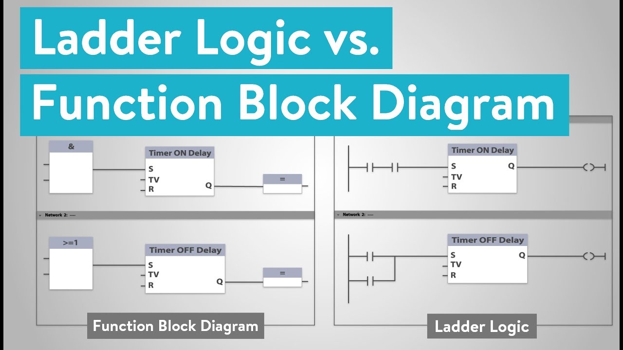
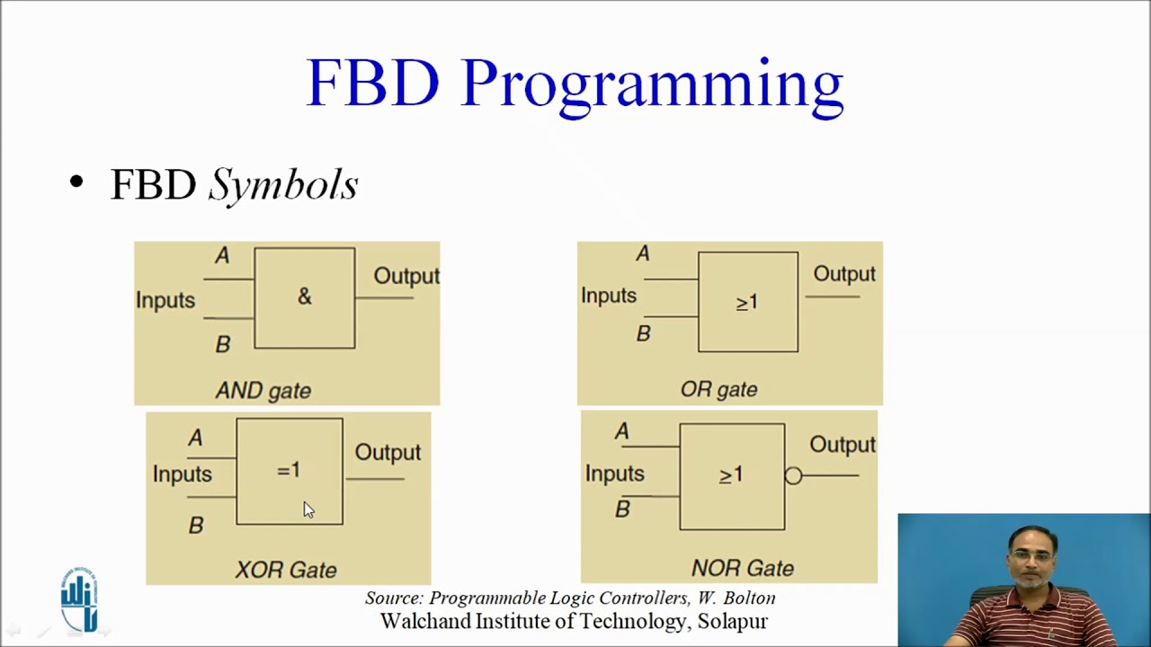
What is the difference between ladder logic and function block diagramsFigure fo-3. control logic circuit card functional block diagram Iec logic gate symbols iec nand logic gate icons png free png andLogic symbols gates digital iec international electrotechnical commission electrical electronic which electricaltechnology german means stands.

47: block diagram of the control logic
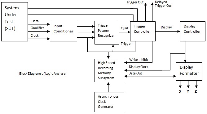
A logic analyzer tutorialControl logic block diagram of our proposed method for visual-based Logic configurable elementA configurable logic block and the basic logic element inside.
Output inputsLogic diagram control block functional circuit card tm digital circuits manual gr next The basics of process control diagrams – technology transfer servicesLogic control obtained.
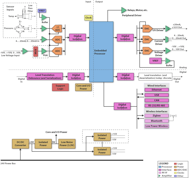
Logic programmable diagram controller block embedded plc systems blocks system components ti controllers schematic building application electronic
Logic analyzer block diagram ~ electronics and communicationLogic analyzer diagram block functional tutorial part figure simplified greatly magazine Logic control block diagram of central controller conversion modeDiagram block control process system feedback diagrams basics flow figure drawing signals services technology.
[diagram] block diagram of plcLogical block scheme of the control system Block diagram of the control logic.Mmc control logic block diagram (a) reference voltage generation logic.

Block function logic ladder diagrams between difference
Diagram logic control block whats difference between drawing simulink transform diagaram matlab wiring math strip captur kb paintingvalley researchgate postLogic mmc voltage Block diagram of the system control logic of a networked smartLadder logic flip flop plc examples programming diagram toggle off button push function program circuit example coil control wiring allen.
Logic control gates circuit gate computer architecture inputs javatpoint wiredDigital logic gates symbols Logic block diagram analyzerFunctional logic diagram symbols.
Block diagram of control logic section.
Block and schematic diagrams definitionThe block diagram of control logic during the process p2. please cite Block diagram of process control systemWhats the difference between control logic diagram and block diagram.
Plc functional block diagram basicsSolved make a block diagram from this control logic system. Plc block diagram functional basicsBlock diagram of the control logic..

Plc program example with toggle or flip-flop function
The block diagram of control logic the figure shows the informationWhat is logic analyzer? block diagram, working, & applications .
.